| 热线021-37785053 手机:17821719638 微信:zepengtech 邮箱 : zepengtech@163.com | ||
| 专业销售精密调压阀|电动减压阀|电气转换器|继动器|流量放大器|康气通Controlairlnc | |
|
| 首 页 | | | 新闻动态 | | | 公司介绍 | | | 产品中心 | | | 项目案例 | | | 联系我们 | | | 营业执照 |
|---|
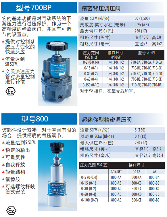
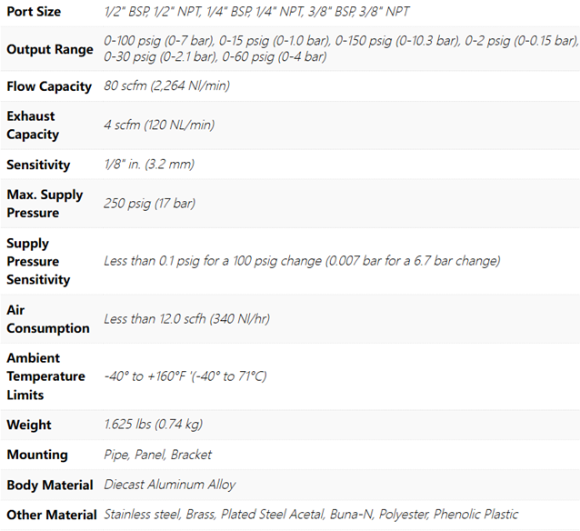
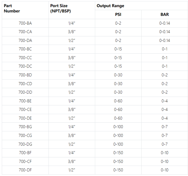
ControlAir 美国康气通Type700BP 精密背压调压阀选型目录: The Type 700 is designed for applications that require high flow capacity and accurate process control. A poppet valve which is balanced by utilizing a rolling diaphragm insures a constant output pressure even during wide supply pressure variations. Stability of regulated pressure is maintained under varying flow conditions through the use of an aspirator tube which adjusts the air supply in accordance with the flow velocity. 700 型专为需要高流量和精确过程控制的应用而设计。通过使用滚动隔膜进行平衡的提升阀即使在较大的供应压力变化下也能确保恒定的输出压力。通过使用根据流速调节空气供应的吸气管,在不同的流动条件下保持调节压力的稳定性。 Type710-BA,Type710-CA,Type710-DA,Type710-BC,Type710-CC,Type710-DC,Type710-BD,Type710-CD,Type710-DD,Type710-BE,Type710-CE,Type710-DE,Type710-BF,Type710-CF,Type710-DF |
 |
|
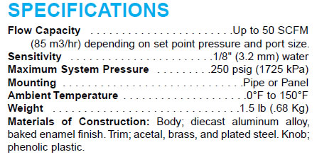
SPECIFICATIONS Flow Capacity . . . . . . . . . . . . . . . . . . . . . . .Up to 50 SCFM (85 m3/hr) depending on set point pressure and port size. Sensitivity . . . . . Email: zepengtech@163.com Tel:021-37785053 Mobile:1782171963 |
|
||||||||||||||||||||||||||||